Interrupts and communication

Gaël Thomas

Mathieu Bacou

Communication buses

Communication buses

  • Hardware components communicate via buses

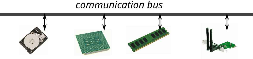
  • From a software point of view, 3 main buses
    • Memory bus: mainly to access memory
    • Input / output bus: messages from CPUs to devices
    • Interrupt bus: messages from peripherals to CPUs
  • From the hardware point of view: a set of hardware buses with different protocols that can multiplex the software buses

The memory bus

  • Processors use the memory bus for reads / writes
    • Sender: the processor or a peripheral
    • Receiver: most often memory, but can also be a device (memory-mapped IO)

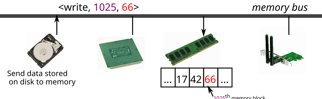
DMA: Direct Memory Access

  • Devices use the memory bus for reads/writes

    • Sender: a processor or a peripheral
    • Receiver: most often memory, but can also be a device (memory-mapped IO)
  • The DMA controller manages the transfer between peripherals or memory

    • The processor configures the DMA controller
    • The DMA controller performs the transfer
    • When finished, the DMA controller generates an interrupt

    –> The processor can execute instructions during an I/O

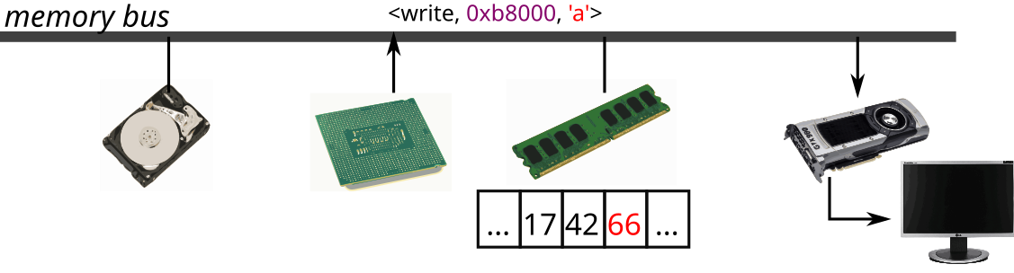
MMIO: Memory-Mapped IO

  • Processors use memory bus to access devices

    • Sender: a processor or a peripheral
    • Receiver: most often memory, but can also be a device (memory-mapped IO)
  • Device memory is mapped in memory

    • When the processor accesses this memory area, the data is transferred from / to the device

The input / output bus

  • Request / response protocol, special instructions in/out

    • Sender: a processor
    • Receiver: a peripheral
    • Examples: activate the caps-lock LED, start a DMA transfer, read the key pressed on a keyboard …

The interrupt bus - principle

  • Used to signal an event to a processor
    • Sender: a peripheral or a processor
    • Receiver: a processor
    • Examples: keyboard key pressed, end of a DMA transfer, millisecond elapsed …
    • IRQ (Interrupt ReQuest): interrupt number. Identifies the sending device

Interrupts

Receiving an interrupt: simple routing

  • Devices are wired to a Platform-Level Interrupt Controller (PLIC)
    • IRQ: input wire number of a device on the PLIC
    • The configuration of the PLIC is done by MMIO
    • The PLIC is wired to every processor to actually interrupt them
  • The OS configures interrupts for each processor and each privilege mode
    • IRQ routing is achieved by selecting which processors receive which interrupts
    • There are also priorities of interrupts
  • The OS sets its interrupt handler by writing its address in register stvec
    • An interrupt handler (a function) usually checks the interrupt type (e.g., device, timer, etc.), and then delegates handling to other functions
    • Depending on the context (typically, user or system mode), the OS swaps handler

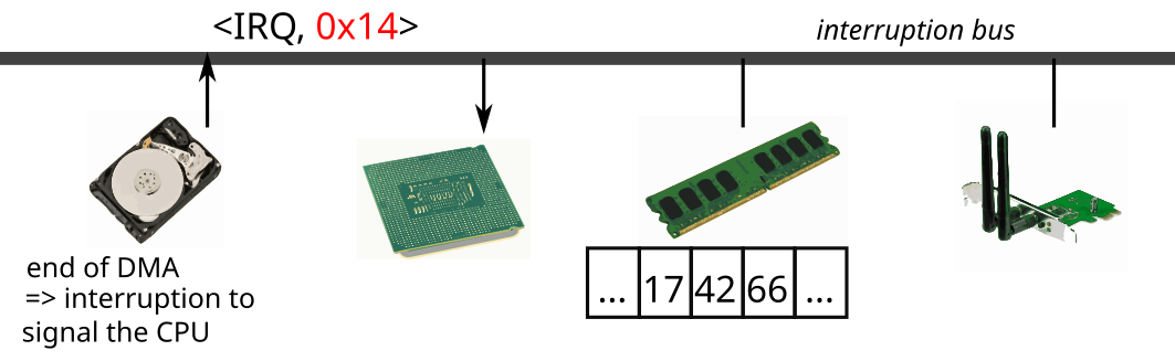
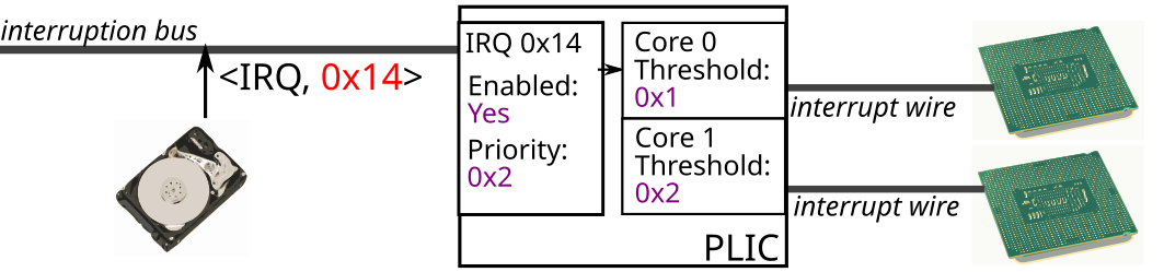
Receiving an interrupt: example

  1. A block device on IRQ line 0X14 signals a data block is available
  2. The PLIC reads the configured priority of IRQ 0x14: 0x2
  3. The PLIC signals all processors with priority threshold < 0x2
  4. All signaled processors compete to serve the interrupt
    • The first processor that gets to serve the interrupt (i.e., execute its interrupt handler) writes to the PLIC to indicate the interrupt is served
    • Other signaled processors check that the interrupt is not already served, and resume normal operation if it is

Receiving an interrupt: simple routing (continued)

  • In the processor, after executing
    1. Check if an interrupt has been received
    2. If so, switch to kernel mode and run the interrupt handler
    3. Then switch back to the previous mode and continue the execution
  • Note: a handler can be run at
    • Problem of concurrent access between handlers and the rest of the kernel code
    • The solution is to mask interrupts, two ways:
      1. raise priority threshold of IRQs accepted by the processor
      2. disable them by clearing bit SIE (Supervisor Interrupts Enable) in register SSTATUS

Receiving an interrupt (continued)

  • In the processor, after executing each instruction

    • Check if an interrupt has been received
    • If so, find the address of the associated handler
    • Switch to kernel mode and run the interrupt handler
    • Then swicth back to the previous mode and continue the execution
  • Note: a handler can be run anytime

    • Problem of concurrent access between handlers and the rest of the kernel code
    • Solution: masking interrupts (cli / sti)

MSI: Message Signaling Interrupt for advanced interrupt management

  • MSI: direct interrupts from devices to processors
    • Each processor has its own IMSIC (Incoming MSI Controller)
    • Different from the PLIC interrupting processors that may serve an interrupt
  • The OS configures an IMSIC via MMIO to enable or disable an interrupt
  • The OS configures a device to direct its interrupts to MSI registers
  • Used for performance or fine granularity in interrupt routing

Inter-core communication

  • One core can send an interrupt to another core: this is called Inter-Processor Interrupt (IPI)
  • Without MSIs:
    • To send an IPI, a processor writes to another processor’s Core-Local Interrupt Controller (CLINT) (in its MMIO registers)
    • The destination processor receives a
  • With MSIs and IMSICs:
    • A processor writes to another processor’s IMSIC like a device

Other interruptions: system calls and exceptions

  • The interrupt handler (the function addressed by register stvec) is also called when system calls and exceptions occur

    • system calls are called by the userspace by executing the instruction ecall, which triggers an interrupt of this type
    • exceptions are faults that occur when executing instructions
      • they trigger an interrupt that matches the fault type
      • for instance, trying to read from an illegal address triggers a software interrupt with exception code 0x5
    • In other words, stvec points to the unique entrypoint into the kernel:
      • from the software, via system calls or IPIs
      • from the hardware, via external interruptions and exceptions

Time management: two sources

  • Jiffies: global time source to update the date

    • A dedicated device or the CLINT regularly sends IRQ
    • Only a single core serves this IRQ to update the date
  • Tick: core-local time source used for scheduling

    • CLINTs are also used to generate periodic interrupts to their cores
    • The system associates a handler with this timer interrupt
    • May be less precise than the